3 Speed Fan Switch Wiring Diagram : 4 Wire Harbor Breeze 3 Speed Ceiling Fan Switch Wiring Diagram Diagram Base Website Wiring Diagram Wiringdiagram Presepeviventebrecciarola It / Ceiling fan wiring diagram 1:. Hi, we have an encon e three speed ceiling fan that quit. To control the power of the fan and lights, two switches and two line wires are used in the two wire configurations. This video describes an easy way to replace a 3 speed ceiling switch. However in sha allah in further post i will explain the fan 5 wire capacitor, regulating speed switch diagram and replacement of fan capacitor in fan motor. For example , when a module is powered up also it sends out a new signal of fifty percent.
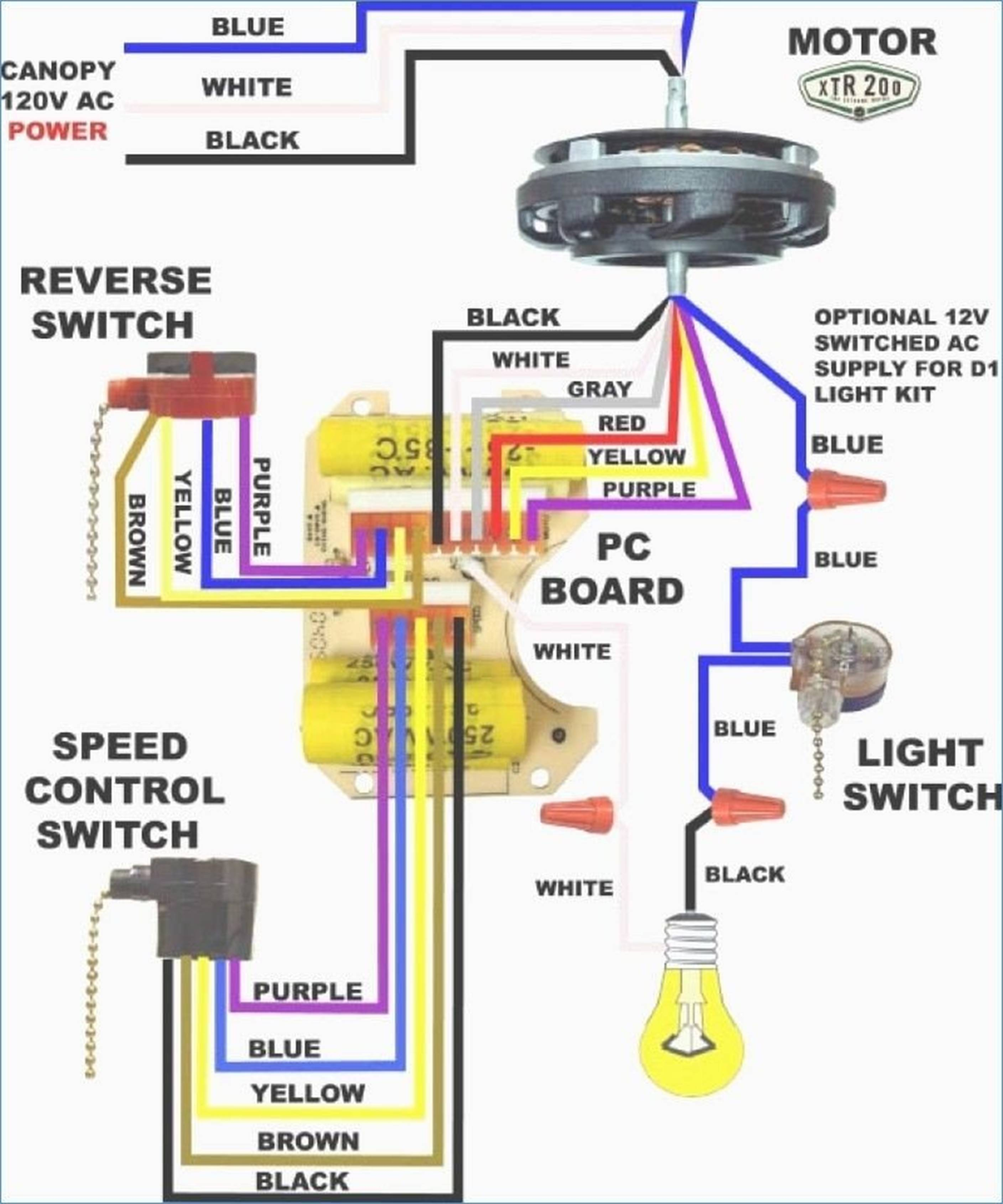
In the above ceiling fan speed control wiring diagram i shown the main winding / running winding and i connect run wire of motor to the speed control switch and you can see it in above diagram that connection of run wire of motor in switch l point and and 1 and 2 for capacitor. We bought a dual capacitor 3 speed fan switch, replaced it wire for i was not able to find a general wiring diagram for these things so i'm. Wiring diagram for 3 speed switch replacement on a ceiling fan. 6a 125vac / 3a 250vac) Just type lsailor1 in the youtube search bar.
Diagram Fan Switch Wiring Diagram On Ceiling Full Version Hd Quality On Ceiling Lawiring Prolocomontefano It from wholefoodsonabudget.com We bought a dual capacitor 3 speed fan switch, replaced it wire for wire as it was before. Need a wiring diagram for a hamptonbay ceiling fan pull switch. I have a 3 wire capacitor with a 3speed 4 wire fan switch color coded as fallows,,,l=black,1=red 2=blue 3=white capacitor has, red,blue and white. Ceiling fan wiring diagram 2: Line voltage enters the switch outlet box and the line wire connects to each switch. 4 postion rotary easy quick connect wire termination for quick and painless installs (just. Ceiling fan switch wiring diagrams 1 In the above ceiling fan speed control wiring diagram i shown the main winding / running winding and i connect run wire of motor to the speed control switch and you can see it in above diagram that connection of run wire of motor in switch l point and and 1 and 2 for capacitor.
Wiring diagram for 3 speed switch replacement on a ceiling fan.
This diagram should be used as a guide if you can follow this guide at your risk. I am confused because the replacement switch only has 4 input terminals, while the original has 6. Should be a green for ground. Just type lsailor1 in the youtube search bar. A wiring diagram is a streamlined standard pictorial representation of an electric circuit. However in sha allah in further post i will explain the fan 5 wire capacitor, regulating speed switch diagram and replacement of fan capacitor in fan motor. One wire vs two wire switch wall control. Need a wiring diagram for a hamptonbay ceiling fan pull switch. A wiring diagram is a simplified standard pictorial representation of an electric circuit. August 31, 2018 by larry a. You might also like other videos of mine. Our 3 speed fan pull chain broke with the short end of the chain in the housing of the switch. 3 speed fan switch wiring diagram unique 3 speed fan switch 3 speed ceiling fan switches pull chain switch 4 wire wiring 4 wire fan switch inflcmedia co three speed fan switch wiring diagram luxury ceiling fan replacing ceiling fan switch pearshaped info 60 unique 4 wire ceiling fan switch wiring diagram images.
Without seeing the switch you are trying to replace, i would guess that the switch would be the same as the one i have illustrated in this instructable. Ceiling fan switch wiring diagrams 1 A wiring diagram is a simplified standard pictorial representation of an electrical circuit. A wiring diagram is a streamlined standard pictorial representation of an electric circuit. Our 3 speed fan pull chain broke with the short end of the chain in the housing of the switch.
How To Replace A Three Speed Ceiling Fan Switch The Easy Way Youtube from i.ytimg.com Black speed switch with only three terminals connected, two wire capacitor. Assortment of hunter 3 speed fan switch wiring diagram. If you do attempt to replace yours, just be sure to take photos of yours for reference before removing it. I figured i screwed something up so i played with the wiring. In the above ceiling fan speed control wiring diagram i shown the main winding / running winding and i connect run wire of motor to the speed control switch and you can see it in above diagram that connection of run wire of motor in switch l point and and 1 and 2 for capacitor. Just type lsailor1 in the youtube search bar. To control the power of the fan and lights, two switches and two line wires are used in the two wire configurations. The l stands for load which is the black wire.
I was wondering if anyone could help me determine:
In the above ceiling fan speed control wiring diagram i shown the main winding / running winding and i connect run wire of motor to the speed control switch and you can see it in above diagram that connection of run wire of motor in switch l point and and 1 and 2 for capacitor. Collection of ceiling fan 3 speed wall switch wiring diagram. First of all, you need to read the disclaimer for this diagram. 1,2,3 are the fan speed control wires. If you do attempt to replace yours, just be sure to take photos of yours for reference before removing it. There are lots of videos on ceiling fan switches, but here's one more. I figured i screwed something up so i played with the wiring. Let me know what you think. A wiring diagram is a streamlined standard pictorial representation of an electric circuit. Need a wiring diagram for a hamptonbay ceiling fan pull switch. Ceiling fan wiring diagram 2: It shows the parts of the circuit as simplified forms, and the power and signal links between the gadgets. The motor will also have three speed wires and one neutral wire.
I hope it helps you. To control the power of the fan and lights, two switches and two line wires are used in the two wire configurations. One wire vs two wire switch wall control. 6a 125vac / 3a 250vac) We bought a dual capacitor 3 speed fan switch, replaced it wire for i was not able to find a general wiring diagram for these things so i'm.
Diagram Hampton Bay Ceiling Fans Wiring Diagram 3 Speed Full Version Hd Quality 3 Speed Diagrammahn Smartgioiosa It from annawiringdiagram.com A wiring diagram is a simplified standard pictorial representation of an electrical circuit. This diagram should be used as a guide if you can follow this guide at your risk. Without seeing the switch you are trying to replace, i would guess that the switch would be the same as the one i have illustrated in this instructable. One wire vs two wire switch wall control. We bought a dual capacitor 3 speed fan switch, replaced it wire for wire as it was before. As i shown in the above ceiling an 3 wire capacitor diagram that red is common wire and yellow for microfarad and purple for farad. A wiring diagram is a simplified traditional pictorial representation of an electrical circuit. 1,2,3 are the fan speed control wires.
For example , when a module is powered up also it sends out a new signal of fifty percent.
Line voltage enters the switch outlet box and the line wire connects to each switch. We bought a dual capacitor 3 speed fan switch, replaced it wire for i was not able to find a general wiring diagram for these things so i'm. Without seeing the switch you are trying to replace, i would guess that the switch would be the same as the one i have illustrated in this instructable. There are no wiring diagrams or instructions for the new switch. Get it as soon as fri, jan 15. It reveals the elements of the circuit as streamlined forms, and the power as well as signal links between the tools. I am confused because the replacement switch only has 4 input terminals, while the original has 6. It shows the parts of the circuit as simplified forms, and the power and signal links between the gadgets. It shows the components of the circuit as streamlined shapes, and the power and signal connections in between the devices. I was wondering if anyone could help me determine: To control the power of the fan and lights, two switches and two line wires are used in the two wire configurations. Assortment of hunter 3 speed fan switch wiring diagram. For example , when a module is powered up also it sends out a new signal of fifty percent.