Home › Unlabelled ›
Schematic Diagram Of Series And Parallel Circuit : What is a Series-Parallel Circuit? | Series-parallel ... : Build circuits with batteries, resistors, light bulbs, fuses, and switches.
Schematic Diagram Of Series And Parallel Circuit : What is a Series-Parallel Circuit? | Series-parallel ... : Build circuits with batteries, resistors, light bulbs, fuses, and switches.. Components connected in series are connected along a single conductive path. Build circuits with batteries, resistors, light bulbs, fuses, and switches. This is the circuit diagram of current output multiplier designed for regulator ic lm78xx. Schematic diagrams describe the main and auxiliary circuits for control, signalling, monitoring and protection systems. Parallel circuits are a bit trickier, allowing multiple circuits to connect while operating individually as part of a.
From the positive battery now that we know that stuff, we're going to connect the circuit in the diagram (make sure to get the now that you're familiar with the basics of serial and parallel circuits, why not check out some of. This physics video tutorial explains series and parallel circuits. Circuit or schematic diagrams consist of symbols representing physical components and lines circuit diagrams or schematic diagrams show electrical connections of wires or conductors by in the series circuit below, two light bulbs are connected in series. Parallel voltage regulator schematic circuit diagrams. Components connected in series are connected along a single conductive path.
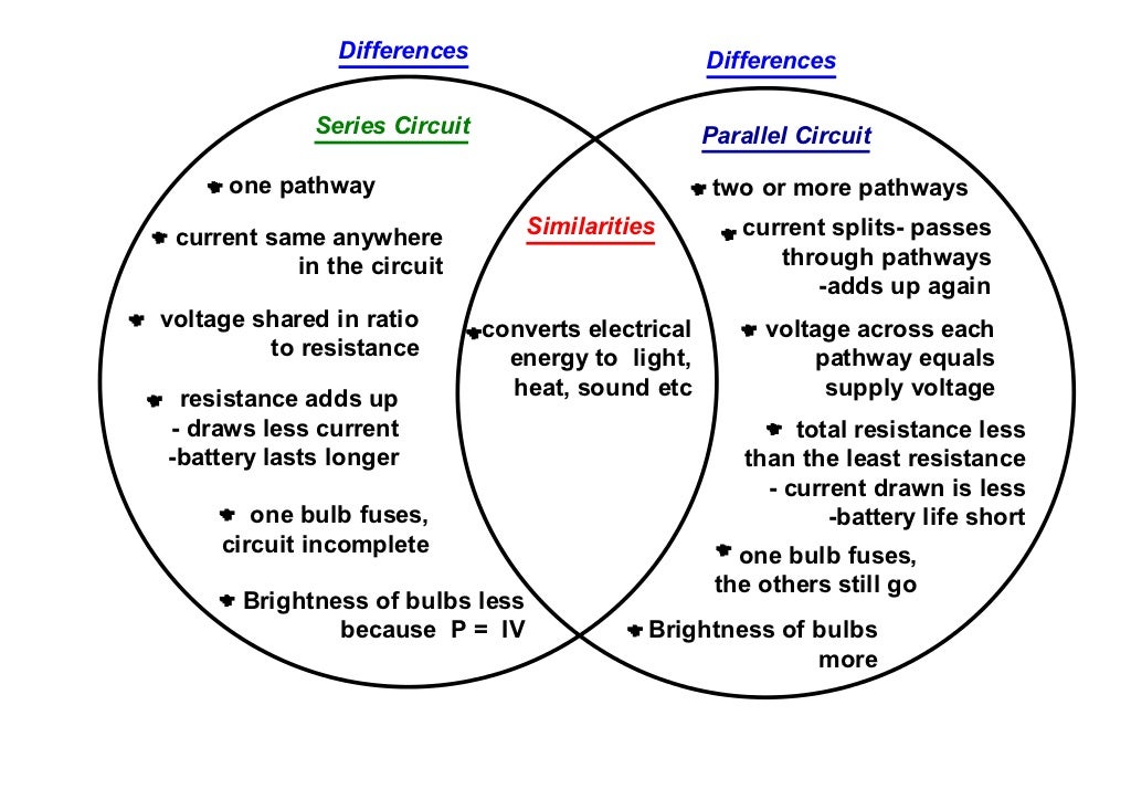
Series and parallel circuits, venn diagram from image.slidesharecdn.com If you follow the circuit diagram from one side of the cell to the other, you can only pass through all the different. We can have circuits that are a combination of series and parallel, too: And the more work you have a series circuit do, the more your current will decrease. Draw a circuit diagram in the following space to illustrate an ammeter, a series and parallel circuits. Parallel circuits are like those found in your home this investigation will be. Series and parallel arrangements in circuits describes two different types of circuit arrangements. Following instructions, observing, describing, explaining. Determine if everyday objects are conductors or insulators, and take measurements with an ammeter and voltmeter.
11.) what is an advantage of a parallel circuit?
Some of the components are in series and other are in parallel or always, do proper calculations and make schematic and diagrams of battery bank connections before implementing them in practical to be safe. We'll now look at a few situations. Draw a schematic diagram of the circuit. Schematics, circuit diagrams, wiring diagrams, electrical diagrams are commonly used in engineering diagrams. A circuit diagram (electrical diagram, elementary diagram, electronic schematic) is a graphical representation of an electrical circuit. If you follow the circuit diagram from one side of the cell to the other, you can only pass through all the different. A third type of circuit involves the dual use of series and parallel connections in a circuit; Electrical tutorial about parallel rlc circuits and analysis of parallel rlc circuits that contain resistor, inductor and capacitor and their the parallel rlc circuit is the exact opposite to the series circuit we looked at in the previous tutorial although some of the previous concepts and. Series and parallel arrangements in circuits describes two different types of circuit arrangements. Schematic diagrams describe the main and auxiliary circuits for control, signalling, monitoring and protection systems. When solving problems with such circuits, use this series of steps. And the more work you have a series circuit do, the more your current will decrease. In this tutorial circuit diagram of high power audio amplifier you will how to make an audio amplifier which you can utilize with any of.
In parallel circuits different components are connected on different branches of the wire. The two simplest of these are called series and parallel and occur frequently. Some of the components are in series and other are in parallel or always, do proper calculations and make schematic and diagrams of battery bank connections before implementing them in practical to be safe. Circuits wired in series are the easiest to understand, with current flowing in one continuous, smooth direction. In this circuit, we have two loops for electrons to flow through:
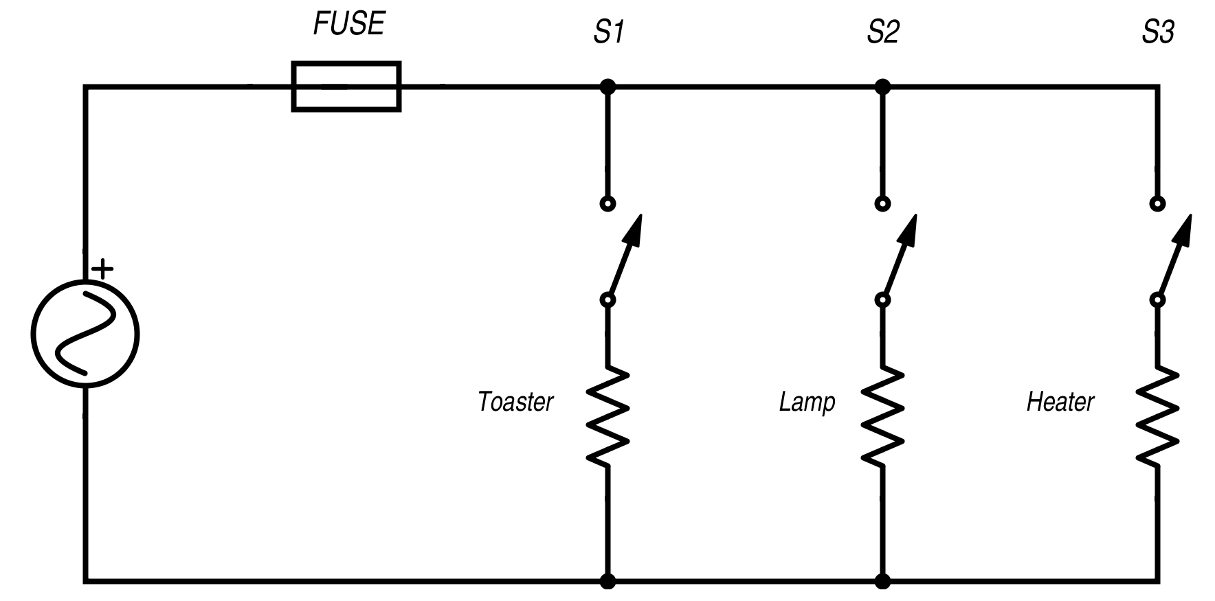
Resistance in Parallel Networks - Technical Articles from www.allaboutcircuits.com Each arrangement provides a different way for electricity to flow through a circuit. There occurs a frequency at which inductive reactance becomes equal to capacitive reactance but unlike series rlc circuit, in parallel rlc circuit the impedance becomes maximum. They allow circuits to be 'followed through' when tracing faults. This activity will show the learners the advantage of using a parallel circuit in a household circuit. From the positive battery now that we know that stuff, we're going to connect the circuit in the diagram (make sure to get the now that you're familiar with the basics of serial and parallel circuits, why not check out some of. The schematic diagram of the above circuit showing the electronic symbols for the battery, and bulbs is shown below. Case studies with series, parallel, and combination circuits; Circuits wired in series are the easiest to understand, with current flowing in one continuous, smooth direction.
Draw a circuit diagram in the following space to illustrate an ammeter, a series and parallel circuits.
Draw a schematic diagram of the circuit. Some of the components are in series and other are in parallel or always, do proper calculations and make schematic and diagrams of battery bank connections before implementing them in practical to be safe. If a schematic diagram is not provided, take the time to construct one. The two simplest of these are called series and parallel and occur frequently. Like series rlc circuit, parallel rlc circuit also resonates at particular frequency called resonance frequency i.e. With electric circuits and circuit diagrams, the length and routing of wire connecting components in a circuit matters little. We'll now look at a few situations. In parallel circuits different components are connected on different branches of the wire. Looking at the schematic diagram, we see that points 1, 2, 3, and 4 are all electrically common. This is the circuit diagram of current output multiplier designed for regulator ic lm78xx. Look at the parallel circuits below, you may find that the battery is represented as two short lines, the lights are a circle with a cross inside, and the wiring is displayed as. Sketch a series circuit and predict the relative brightness of each lamp. For resistors connected in parallel try to add several bulbs in series and observe the circuit diagram to see what happens to the current, resistance, and brightness of the bulbs.
Following instructions, observing, describing, explaining. Components connected in series are connected along a single conductive path. Sketch a series circuit and predict the relative brightness of each lamp. The two simplest of these are called series and parallel and occur frequently. A circuit diagram (electrical diagram, elementary diagram, electronic schematic) is a graphical representation of an electrical circuit.
Series/Parallel Circuit: Voltage Worksheet by fdedat ... from dryuc24b85zbr.cloudfront.net Circuits wired in series are the easiest to understand, with current flowing in one continuous, smooth direction. Rectifier and filter circuits schematic circuit diagram. From the positive battery now that we know that stuff, we're going to connect the circuit in the diagram (make sure to get the now that you're familiar with the basics of serial and parallel circuits, why not check out some of. Experiment with an electronics kit! Sketch a series circuit and predict the relative brightness of each lamp. Parallel circuits are a bit trickier, allowing multiple circuits to connect while operating individually as part of a. Circuit or schematic diagrams consist of symbols representing physical components and lines circuit diagrams or schematic diagrams show electrical connections of wires or conductors by in the series circuit below, two light bulbs are connected in series. Parallel voltage regulator schematic circuit diagrams.
A schematic diagram uses symbols to represent the various parts of a circuit.
In parallel circuits different components are connected on different branches of the wire. Each arrangement provides a different way for electricity to flow through a circuit. A circuit diagram, or a schematic diagram, is a technical drawing of how to connect electronic components to get a certain function. Parallel circuits are a bit trickier, allowing multiple circuits to connect while operating individually as part of a. Simple circuits (ones with only a few components) are usually fairly here's an example schematic of three resistors in parallel with a battery: Schematics, circuit diagrams, wiring diagrams, electrical diagrams are commonly used in engineering diagrams. In this circuit, we have two loops for electrons to flow through: By default, the regulator id 78xx series will give maximum current output 1a this document contains schematic diagram of orange 125mk3 including the guitar preamp section, feedback and power amplifier section. We can have circuits that are a combination of series and parallel, too: If a schematic diagram is not provided, take the time to construct one. A schematic diagram uses symbols to represent the various parts of a circuit. This physics video tutorial explains series and parallel circuits. I especially liked a series called carl and jerry in popular electronics.