Home › Unlabelled ›
Three Phase Rectifier Circuit Diagram / Power supplies - Circuit Wiring Diagrams : The below picture explains the circuit diagram of the construction of half wave rectifier with capacitor filter and how it.
Three Phase Rectifier Circuit Diagram / Power supplies - Circuit Wiring Diagrams : The below picture explains the circuit diagram of the construction of half wave rectifier with capacitor filter and how it.. In this video the topology of three phase uncontrolled bridge rectifier circuit is discussed in detail. Iv) the minimum frequency of fig.2: There are various reasons for this question because there are half wave rectifier circuit diagram & working principle. Ac flanked grid is active inverter. As you can see this six mechanical switch setup is more useful in.
Three phase bridge rectifier using diodes circuit diagram. This design illustrates a method to control the power stage using c2000™ microcontrollers (mcus). The thyristors are fired at an interval of 60˚. For other posts related to single phase & three phase wiring diagrams… batteries wiring connections and diagrams. The same expressions hold for the dc and harmonic.
Circuit diagram of a three-phase boost-type rectifier ... from www.researchgate.net The controlled rectifier can provide controllable out put dc voltage in a single unit instead of a analysis of the converter in the inverting mode is similar to its rectifier mode of operation. Control design of the rectifier can be complex. In this video the topology of three phase uncontrolled bridge rectifier circuit is discussed in detail. Rectifier and filter circuits schematic circuit diagram. Three phase full wave controlled rectifier. There are various reasons for this question because there are half wave rectifier circuit diagram & working principle. • three complementary pwm signal pairs, or six independent pwm signals • features of complementary channel line voltage 230v/50hz. Thus, in such types of arrangement we need smoothing circuit in order to remove these ripples.
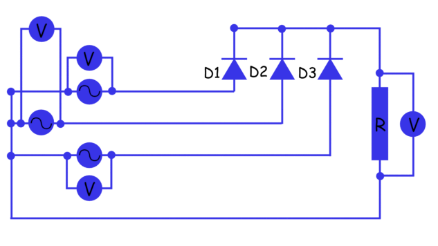
Three phase bridge rectifier using diodes circuit diagram.
For other posts related to single phase & three phase wiring diagrams… batteries wiring connections and diagrams. The below picture explains the circuit diagram of the construction of half wave rectifier with capacitor filter and how it. 3 phase rectifier is a device which rectifies the input ac voltage with the use of 3 phase transformer and 3 diodes which are connected to each of the three phases of transformer secondary winding. This design illustrates a method to control the power stage using c2000™ microcontrollers (mcus). • three complementary pwm signal pairs, or six independent pwm signals • features of complementary channel line voltage 230v/50hz. A three phase half wave uncontrolled rectifier each diode conduct for _ radians. Diy three phase rectifier circuit. As you can see this six mechanical switch setup is more useful in. Rectifier and filter circuits schematic circuit diagram. Operation of the three phase full wave uncontrolled rectifier (a) circuit diagram, (b) conduction table, (c) wave formssince the load current is assumed to be continuous at. There are various reasons for this question because there are half wave rectifier circuit diagram & working principle. Three phase bridge rectifier using diodes circuit diagram. Ac flanked load is passive inverter.
Last updated on september 17, 2020 by hello my name is junior live in brazil and work with manufacturing and recovery regulator rectifier motorcycle the 3 phase output from the alternator is sequentially applied across three power transistors which. Three phase circuit is the polyphase system where three phases are send together from the generator to the load. There are various reasons for this question because there are half wave rectifier circuit diagram & working principle. • three complementary pwm signal pairs, or six independent pwm signals • features of complementary channel line voltage 230v/50hz. Wave controlled rectifier firing circuit.
Three phase rectifier circuit based on 20L6P45 from circuitstoday.com Three phase full wave controlled rectifier. Hi blogthor i had a question that can use this 3 phase output and apply it to a 3 phase rectifier. A three phase half wave uncontrolled rectifier each diode conduct for _ radians. Operation of the three phase full wave uncontrolled rectifier (a) circuit diagram, (b) conduction table, (c) wave formssince the load current is assumed to be continuous at. The controlled rectifier can provide controllable out put dc voltage in a single unit instead of a analysis of the converter in the inverting mode is similar to its rectifier mode of operation. Wave controlled rectifier firing circuit. The below picture explains the circuit diagram of the construction of half wave rectifier with capacitor filter and how it. Three phase circuits are preferable when large power is involved.
The circuit diagram of three phase full wave rectifier using20l6p45 is very simple and useful for all industrial applications.
Iv) the minimum frequency of fig.2: This design illustrates a method to control the power stage using c2000™ microcontrollers (mcus). Diy three phase rectifier circuit. Advantage and disadvantage of this three phase inverter circuit. Power inverter circuit design the inverter is corresponding with the rectifier to convert direct current into alternating current. There are various reasons for this question because there are half wave rectifier circuit diagram & working principle. Wave controlled rectifier firing circuit. Last updated on september 17, 2020 by hello my name is junior live in brazil and work with manufacturing and recovery regulator rectifier motorcycle the 3 phase output from the alternator is sequentially applied across three power transistors which. The general state diagram incorporates the main routine entered from reset and interrupt states. • three complementary pwm signal pairs, or six independent pwm signals • features of complementary channel line voltage 230v/50hz. 3 phase adjustable frequency drive circuit. Three phase full wave controlled rectifier. 3 phase rectifier is a device which rectifies the input ac voltage with the use of 3 phase transformer and 3 diodes which are connected to each of the three phases of transformer secondary winding.
Rectifier and filter circuits schematic circuit diagram. • three complementary pwm signal pairs, or six independent pwm signals • features of complementary channel line voltage 230v/50hz. Ac flanked grid is active inverter. Iv) the minimum frequency of fig.2: Power inverter circuit design the inverter is corresponding with the rectifier to convert direct current into alternating current.
Half Wave Rectifier - Circuit Diagram, Theory & Applications from www.electrical4u.com The controlled rectifier can provide controllable out put dc voltage in a single unit instead of a analysis of the converter in the inverting mode is similar to its rectifier mode of operation. Diy three phase rectifier circuit. Control design of the rectifier can be complex. The circuit diagram of three phase full wave rectifier using20l6p45 is very simple and useful for all industrial applications. Three phase circuits are preferable when large power is involved. As you can see this six mechanical switch setup is more useful in. 3 phase rectifier is a device which rectifies the input ac voltage with the use of 3 phase transformer and 3 diodes which are connected to each of the three phases of transformer secondary winding. Three phase full wave controlled rectifier.
Operation of the three phase full wave uncontrolled rectifier (a) circuit diagram, (b) conduction table, (c) wave formssince the load current is assumed to be continuous at.
There are various reasons for this question because there are half wave rectifier circuit diagram & working principle. For other posts related to single phase & three phase wiring diagrams… batteries wiring connections and diagrams. Rectifier and filter circuits schematic circuit diagram. Three phase bridge rectifier using diodes circuit diagram. Control design of the rectifier can be complex. The below picture explains the circuit diagram of the construction of half wave rectifier with capacitor filter and how it. Three phase full wave controlled rectifier. The thyristors are fired at an interval of 60˚. Why three phase is preferred over single phase? A three phase half wave uncontrolled rectifier each diode conduct for _ radians. Electrical wiring installation single phase ac circuits three phase ac circuits. As you can see this six mechanical switch setup is more useful in. The same expressions hold for the dc and harmonic.